
The C5 Corvette’s Momemtim Chassis took the Corvette to a whole new level and paved the way for the C5-R Corvette
Dateline: 1-16-20 – Graphics by K. Scott Teeters, Images from GM archives: Structure is everything. Lessons learned from the C5, C6, and C7 Corvettes is that the stiffer the chassis, the better the suspension can be tuned for improved handling. The C1 to C4 chassis’ were fine for their day, but compared to the modern Corvettes, they leave a lot to be desired, especially if bigger tires and more horsepower is applied. The issue of structure is not new; look at what the Greenwood brothers were doing with the chassis of their widebody IMSA Corvettes in the 1970s. The NASCAR cars of the 1970s had fortress-like cages welded to their frames; but you can’t live with structures like that for streetcars. The arrival of the C5 was a quantum leap in terms of structure.
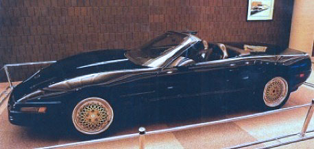
Joe Spielman ran GM’s Midsize Car Division in 1992 and was responsible for forty-percent of the engineering and manufacturing of GM’s auto production. It was a bad time for GM and despite the Corvette’s iconic status; its future was in jeopardy. Spielman created the “Decision Makers” that included himself, Carlisle Davis, John Cafaro, and Dave McLellan. Three possible formats for the C5 Corvette were created. The first format was the “Momentum Architecture” that featured a stiff backbone, front-engine, rear transmission, and an evolutionary body style. The second format was the “Mid-Engine”, favored by McLellan and GM President Jack Smith. The 1990 CERV III wasn’t just a dream car, it was built with manufacturing in mind, but was going to be complex and expensive. The third format was “Stiffer and Lighter”. This would be the least expensive and was a stiffer, lighter version of the C4. Fortunately, the team went with the “Momentum Architecture”.
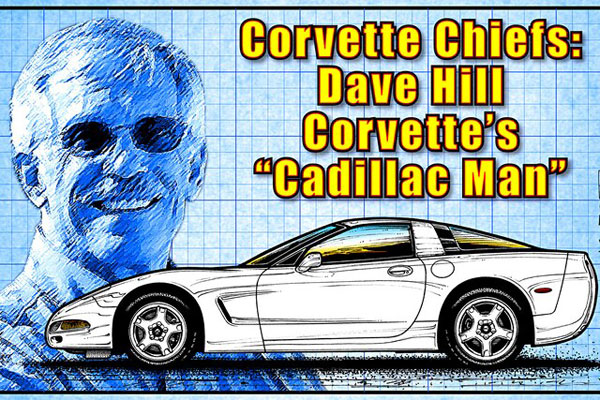
The problem was money. When Dave Hill took over, as Corvette chief engineer in November 1992, his 1993 development budget was just $12 million. The estimated total cost to design and develop the C5 was originally $250 million and was cut back to $150 million; GM was in financial trouble and was cutting everything. But Chevrolet general manager Jim Perkins saved the Corvette by juggling an extra $1.2 million so that Hill could build a demonstration car. Another consideration Perkins wanted to see was a “Billy Bob” no-frills concept. Hill’s demonstration Corvette would become the CERV IV, with a manual transmission. Later Hill build an automatic version called the CERV IVb. The “Billy Bob” concept wasn’t developed until 1998 and became the 1999 Hardtop, that later became the now-legendary Z06.
The CERV IV was a true stealth development car. The chassis had the backbone structure of the proposed “Momentum Architecture” plan, but was clothed in a C4 body so that Hill and his team could drive the car on public roads, as well as the Proving Grounds in Michigan and Arizona. To the public it was just another C4 Corvette. Hill’s objectives for the CERV IV were to; prove to GM’s president Jack Smith that his team could reinvent the car, as well as the building process. When Hill took people for test-drives, they said, “This is like no Corvette we ever felt!” Hill’s plan worked, he got his C5 development budget up to $241 million, and set his team to work.
Hill wanted the C5 to be able to do everything as well as, or better than the C4. The C4 had a 350-mile range; Hill wanted 370 for the C5. The solution to the fuel range was a blessing because instead of one tank mounted on top of the rear of the frame, the C5 has two tank placed low on each side of the transaxle. This also helped lower the C5’s center of gravity. Hill wanted a coefficient of drag of .29, the lowest of any production car at that time, so he had to lean on designer John Carfaro.
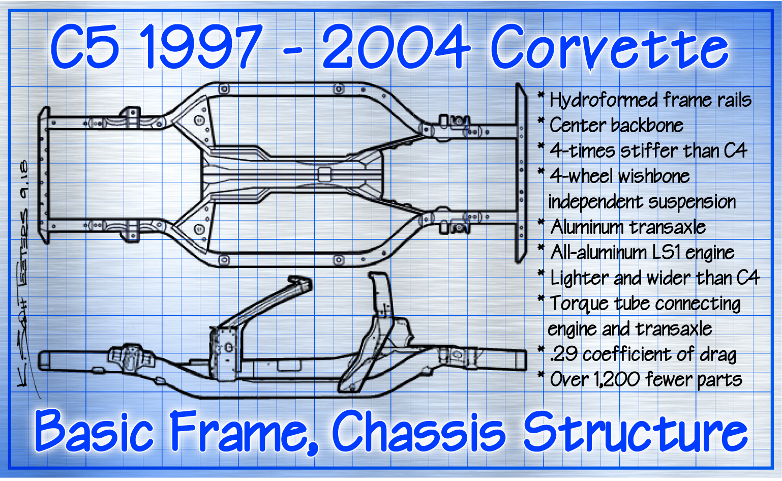
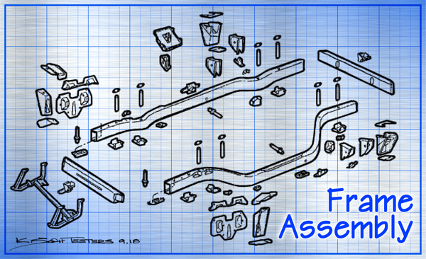
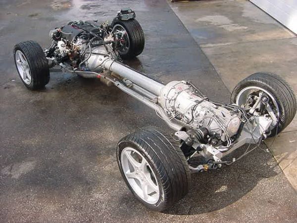
But the piece de resistance of the C5’s new structure was its hydroformed frame. The first mass-produced automotive application of Hydroforming was for the instrument panel support beam in a 1990 Chrysler mini van. The 1997 C5 Corvette was the first mass-produced automobile to use this manufacturing technique on a major structural component. The frames of all pervious Corvettes were made from sheet steel, bent to form a box section. The box sections were then welded together to form the side rails and cross members. Hydroforming creates complex shapes that are stronger, lighter, and more rigid. After engineers designed the shape of the C5’s frame rails, sheet steel was rolled into a tube, laser-welded, and bent into the basic shape of the frame rail. The shaped tube was then placed inside a form and sealed. Water was then pumped into the tube at 7,000 psi that inflated the steel into the shape. The finished side rail was one, 13-foot long piece, instead of many boxed pieces all welded together. The crossmembers and attachment brackets, (36 pieces in total) were welded by robotic and human welders. Convertibles have 33 parts, one extra for the tonneau cover latch.

The second major structural component on the new C5 was the longitudinal center tunnel backbone. This kind of construction had then only been seen on exotic supercars and racecars. The center backbone creates the driveshaft tunnel and locks the front and rear of the frame together. The C4 designers had a long driveline support torque bar that bolted to the end of the transmission and the rear differential, whereas the designers of the C5 created an enclosed torque tube that bolted to the back of the bellhousing and the front of the transaxle, with a lightweight Metal Matrix Composite (MMC) driveshaft. The torque tube that connects the engine with the transaxle, was then bolted to the frame. Combined with the center backbone, the C5’s chassis structure is four times as stiff as the C4. This was an amazing accomplishment for a mass-produced sportscar.
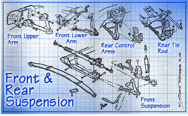
With the strongest structure ever created for a Corvette, Hill’s suspension engineers were better able to design components to fine tune wheel control. Now the suspension didn’t have to compensate for a flexing structure. The selection of springs, dampers, anti-roll bars and bushings can be more accurate. The C4 suspension was very good and is today used often on street rods. The C5 went to the next level with double A-arms on all four corners of the independent suspension. The new aluminum suspension components are made using the then-new process of casting-and-forging to create lighter, stronger parts.
The C5 came with three levels of suspension. The standard FE1 was for basic driving and used specifically selected fiberglass composite leaf springs, shocks, sway bars, and bushings. The $350 optional Z51 suspension had stiffer springs, shocks, and larger-diameter sway bars. Active suspension options had been around since 1989; the new C5 offered the latest version of the F45 Selective Real Time Damping for $1,695. The C5’s basic dimensions tell us a lot. The C5 is 179.4-inches, 1.1-inches longer than the C4; 73.6-inches wide, 2.9-inches wider than the C4; 47.8-inches in height, 1.5-inches taller than the C4; 104.5-inch wheelbase, 8.3-inches longer than the C4; and 3,221-pounds, 77-pounds lighter than the C4. Wider, lighter, stiffer, with an all-aluminum engine, transaxle, and over 1,200 fewer parts, the C5 was the most revolutionary Corvette to date. – Scott

Corvette Chassis History, Pt 1 – C1 Chassis – HERE
Corvette Chassis History, Pt 2 – C2/C3 Chassis – HERE
Corvette Chassis History, Pt 3 – C4 Chassis – HERE
Corvette Chassis History, Pt 4 – C5 Chassis – HERE
Corvette Chassis History, Pt 5 – C6 Chassis – HERE
Corvette Chassis History, Pt 6 – C7 Chassis – HERE