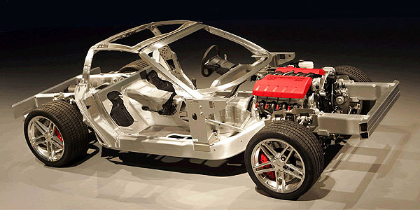
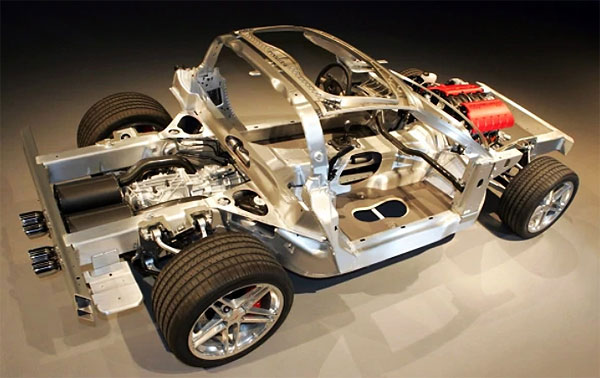
Dave Hill’s 2006 Z06 stunned everyone with its stiffer than stock aluminum frame.
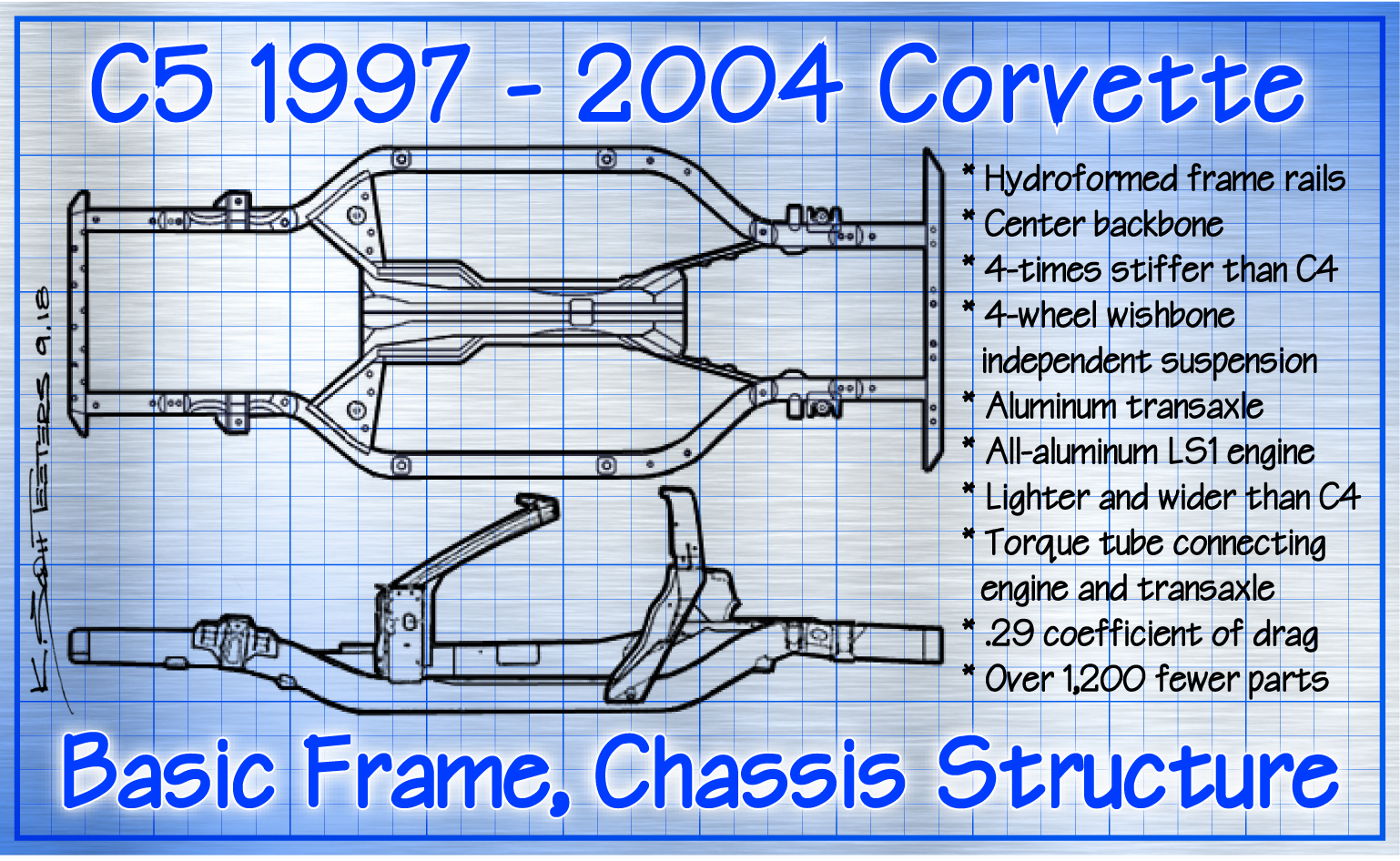
Dateline: 1.17.20 – Graphics by K. Scott Teeters, Images from GM archives: Corvette fans have been frustrated for years with Chevrolet’s evolutionary Corvettes. The “pie-in-the-sky” mid-engine Corvette has been around since the 1960s and anything less was evolutionary. The pending C8 aside, the C5 was the most revolutionary Corvette; because of the hydroformed steel perimeter frame, center backbone, all-aluminum LS1 fuel-injected engine, and transaxle. The C5 was the most solid Corvette ever offered and allowed engineers to vastly improve the basic suspension, the Z51, and the Z06. The racing C5-R won its class at Daytona in 2001 and 2003; won its class at Sebring in 2002, 2003, and 2004, and won its class at Le Mans in 2001, 2002, and 2004. This never would have happened without the superior basic C5 chassis. Dave Hill’s team got the C5’s chassis design so right that by 1999 they determined that a C6 needed to be started.
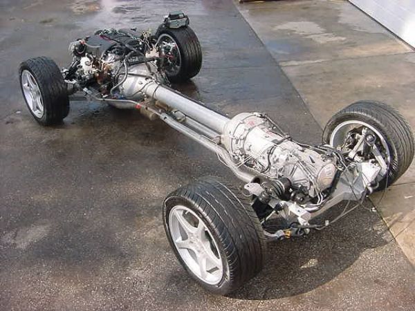
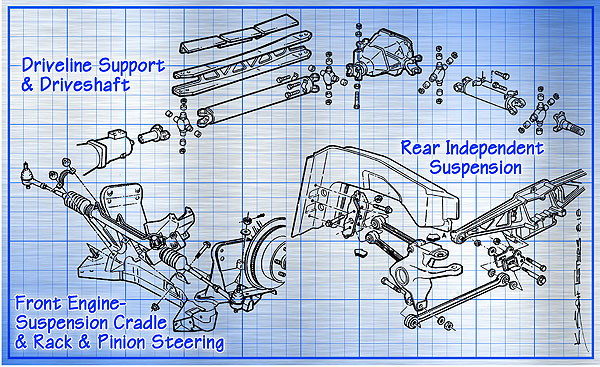
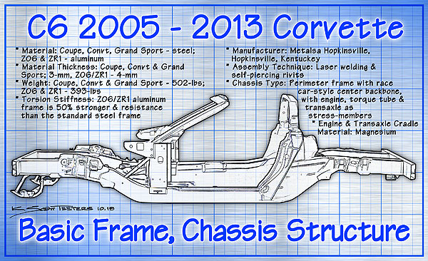
Whereas the C5 structure was revolutionary, the C6 was evolutionary. While the C6 chassis is different from the C5, it is essentially the same hydroformed steel perimeter frame with a center backbone, with the engine, torque tube, and transaxle all as stress members of the overall structure.
Let’s start with the basic C6 chassis. The chassis has a 1.2-inch longer wheelbase of 105.7-inches, but the overall length is 5.1-inches shorter than the C5 chassis. To achieve this, engineers shortened the frame rails 2.4-inches and changed the tube-formed front bumper beam to a unit made with two channels welded together to save 2/3s of an inch. The shorter frame with less overhang on the body achieved a total of 5.1-inches of length on the C6, over that of the C5. The shorter frame also increased the torsional stiffness. And to reduce squeaks, rattles, and vibrations, high-strength steel braces were added to the frame to improve structural rigidity.
Weight savings were picked up by using extruded aluminum beams in the interior instead of the cast aluminum beams from the C5. The instrument panel has additional brackets for the beam under the dashboard. Side-impact beams were made of aluminum and saved 4.5-pounds, plus the doors do not have traditional latch and lock mechanisms. Aluminum braces were used through the structure to improve crash performance. The front skid-bar in front of the radiator is also aluminum. An aluminum panel that saved 1-pound and increased stiffness replaced the steel driveline panel under the driveline torque tube. To increase upper rigidity, the windshield frame has extra gussets. And the trunk uses lightweight plastic braces. Corvette systems engineer Ed Moss said, “We are making it (the C6) smaller, lighter, but stiffer.”
The issue of stiffness in high-powered sports cars with wide tires cannot be under-estimated. Increased grip, torque, and horsepower will put tremendous added stress to a performance car’s structure. Imagine what would happen if a LT5 engine and big tires were applied to a stock C1 chassis. The C5 1999-2000 Corvette Hardtop, with its bolted and bonded hardtop increased the overall structural stiffness by 12-percent, enough to make it an excellent base to build the Z06 upon. The basic C6 platform offered a significant improvement in stiffness that made it an excellent platform to build the Grand Sport that used Z06 suspension parts and wide tires. Without any increase in power, the Grand Sport was a better Corvette. Stiffness matters.

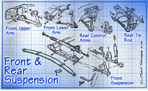
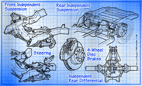
While the C6’s suspension is similar to the C5’s, there are no carryover parts. The basic design of the short-long A-arms, transverse composite leaf springs independent suspension is the same. The control arms, springs, dampers, bushing, sway bars, and steering gear are all completely redesigned. New hub knuckles and dampers allow for greater suspension travel thanks to improved clearance. One issue with C5s was road noise and twitchiness on rough roads. To improve handling and ride, steering geometry and the progressive rates of the composite springs were improved.
Like the C5 the C6 offered customers three levels of suspension performance. Chevrolet calls the basic C6 suspension, “tuned for balance, ride comfort, and precise handling.” This is for the customer that wants a Corvette because they like “driving a Vette” with 400-horsepower on tap when they want a brief thrill, but aren’t interested in exploring the limits of tire grip.

The F55 Magnetic Selective Ride Control was a $1,695 option with some amazing technology. Magnetorheological dampers use metal-infused fluid that controls the viscosity of the fluid with a magnetic field created by an electromagnet. This semi-active suspension adjusts the fluid via a computed to adjust damping rates based on road surfaces down to the millisecond. The active handling and antilock systems were smarter and less intrusive.
And for the enthusiast that doesn’t want to go for the serious big gun Z06, but wants the most from their base model Corvette, there was the $1,495 Z51 Performance Package. The F51 option has been around since 1984 with a starting price of $600 with prices fluctuating through to 1990. Then from 1991 to 1995 Chevrolet offered the $2,045 Z07 Adjustable Suspension Package. The Z51 option was back in 1996 but consisted only of stiffer springs and stabilizer bars for $350 from 1996 to 2003, then $395 in 2003 and 2004.

The Z51 was part of the C6 lineup from 2005 to 2009 and was a whole different animal. Costing $1,495 in 2005, then $1,695 from 2006 to 2009, the Z51 package was the most comprehensive Z51 package ever offered, consisting of; higher rate springs and shocks; larger sway bars; larger cross-drilled rotors – 13.5-inch diameter on the front and larger 13-inch diameter on the rear; coolers for the engine oil, transmission, and power steering; higher-grip Goodyear EMT tires; revised gear ratios for the 6-speed cars.

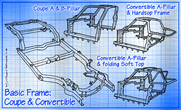
An interregnal part of the overall objective of a smaller, lighter, and stiffer C6 was the body. For the body part of the C6, designers wanted to improve the fit of the body panels and reduce weight. For the broad flat parts, such as the hood, doors, trunk lid and tonneau cover on the convertible, SMC – Sheet Molded Compound was used. This is a fiberglass mixed with resin that is compressed into a mold, with a chemical reaction and the heat from the compression curing the part. For more complex shapes, such as the front grille and the rear fascia, PRIM – Polyurethane-Material Reinforced-Reaction Injection Molding was used. The removable roof panel was made from Polycarbonate, either transparent or painted.

But the major breakthrough for the C6 chassis was the all-aluminum chassis for the Z06 and the ZR1. The basic chassis design is the same except that the hydroformed side rails are made of 4-mm 5745 aluminum alloy. The standard C6 steel frame thickness was 3-mm and weighs 502-pounds while the aluminum Z06 frame weighs 392-pounds; that’s 110-pounds lighter, or 22.5-percent lighter. The Z06 frame is 50-percent stronger in torsional and bending stiffness. The Metalso Metal Fabricator, in Hopkinsville, Kentucky manufactured the aluminum frames and then shipped them to the Corvette Bowling Green assembly plant. The engine cradle and fixed-roof panel are magnesium, and the floorboards were carbon fiber.
Everything tends to move upward in the world of Corvettes. When the Z06 debuted in 2006, no one imagined that the C7 base Corvette would ride on a C6 Z06-like chassis.
Scott

Corvette Chassis History, Pt 1 – C1 Chassis – HERE
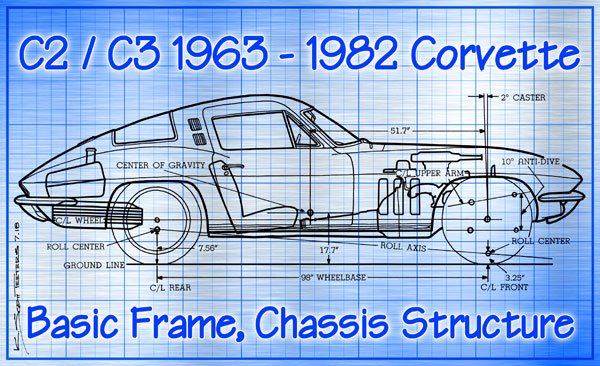
Corvette Chassis History, Pt 2 – C2/C3 Chassis – HERE
Corvette Chassis History, Pt 3 – C4 Chassis – HERE
Corvette Chassis History, Pt 4 – C5 Chassis – HERE
Corvette Chassis History, Pt 6 – C7 Chassis – HERE